

Innovation in Sweeper Technology


Project Description
01 / Situation
As a newly founded team of engineers, our goal was to design a street sweeper for outdoor areas. The main goal of this project was to further critical thinking and understanding of engineering concepts by applying theoretical knowledge from the lectures onto a practical example from the real world. Each team was given freedom on the overall application purpose of their sweeper and lifetime.
02 / Restrictions
As part of the design process, several components were to be "purchased" externally including a Honda GX120 Engine, the seat, wheels and air filtration system. As such, these subsystems were not designed during the project. Additionally, certain size restrictions were provided to the sweeper with additional design restrictions on the motion of the sweeper brushes.
03 / Project Steps
As this was an academic project, several guidelines and regulations had to be followed. The design process was based on a didactic approach, requiring initial principal concepts which were then transferred into full technical drawings (by hand) and eventually CAD models. As part of this project, several dimensioning procedures were carried out; the dimensioning of shafts, springs, bearings and bolted connections.
As part of the Mechanical Engineering course, all Semester 3 and 4 students take part in a large group project in Mechanical Design. The project lasts over the course of 2 Semesters (6 months).
Design Solution
Design Philosophy of the ST-16
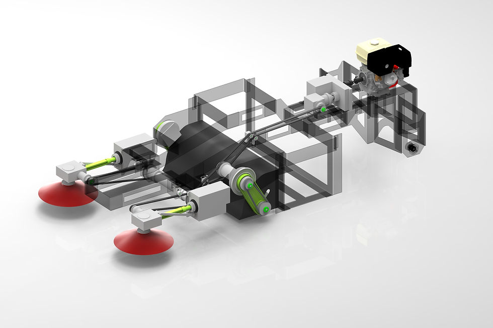
From the beginning of the project, our design philospohy was geared towards a few simple criteria: maintainability, creativity and functionality. We were aware that in the real world, cost and implementability are key factors that are considered during the design process, however for the scope of this project these criteria were only considered of secodnary importance. Instead, a bigger focus was put on coming up with creative solutions that would challenge our own understanding of the concepts taught during the lectures and to provide an additional challenge to the project. All these ideas and concepts have been incorporated into our first design iteration of the ST-16 Street Sweeper. The entire sweeper was designed from the ground up, starting with the frame, drive system, brush system, container system, steering system and even seating and interface concept. The main sub-systems will be expanded upon in the following section.


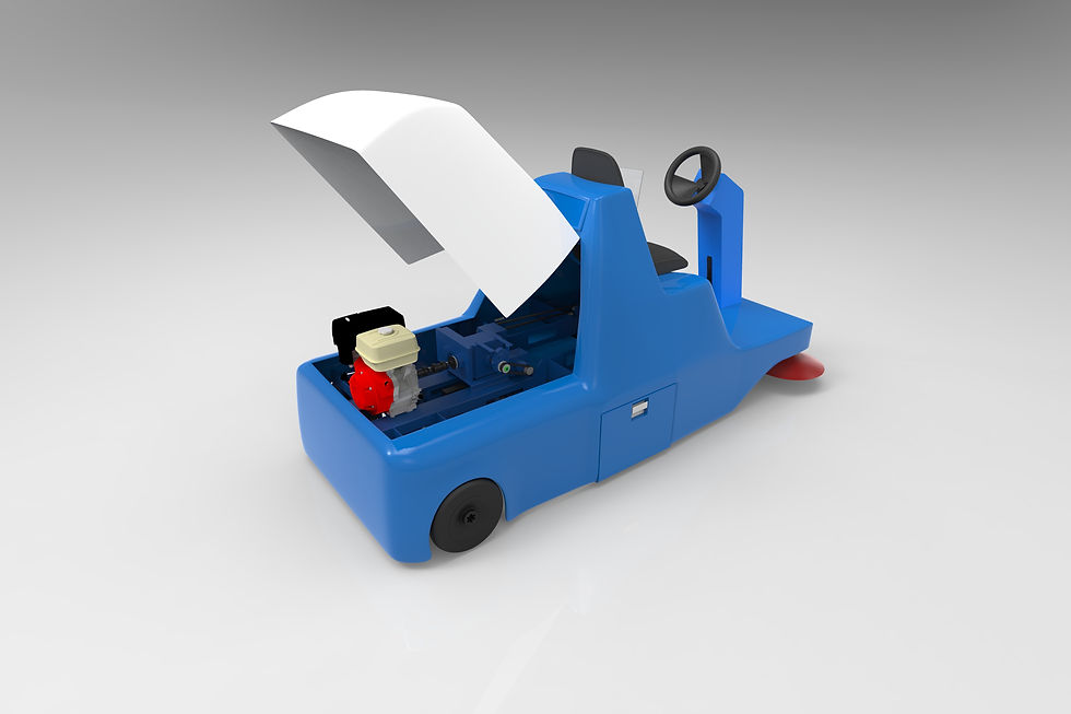
Presenting the ST-16

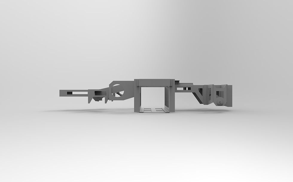
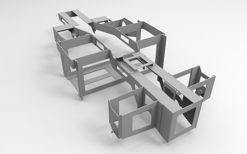
ST-16 Frame
The entire backbone which all other sub-systems rely on is the frame of the ST-16. One of the big design restrictions was that, due to low production volume, a casted frame construction was not possible. This left two frame design alternatives. One option was a welded beam frame design and the other a main frame design which makes use of bolted and welded connections. The final design choice was to go with a hybrid construction making use of large steel plates that are pre-cut into the desired shapes and then assembled or welded together. The advantage of this design is that it does not required the design of a special welding frame, is easily expandable with additional frame components and with further refinement can lead to a weight reduction in comparison to standard welded frame constructions. Additionally, the seperate frame components in crucial cases can be mounted using botled connections with polymer inlays in order to dampen system vibrations coming from the road, drive train and brush systems. Another benefit of the hybrid frame design is the ability to exchange selected frame parts after collisions or for upgrade purposes.

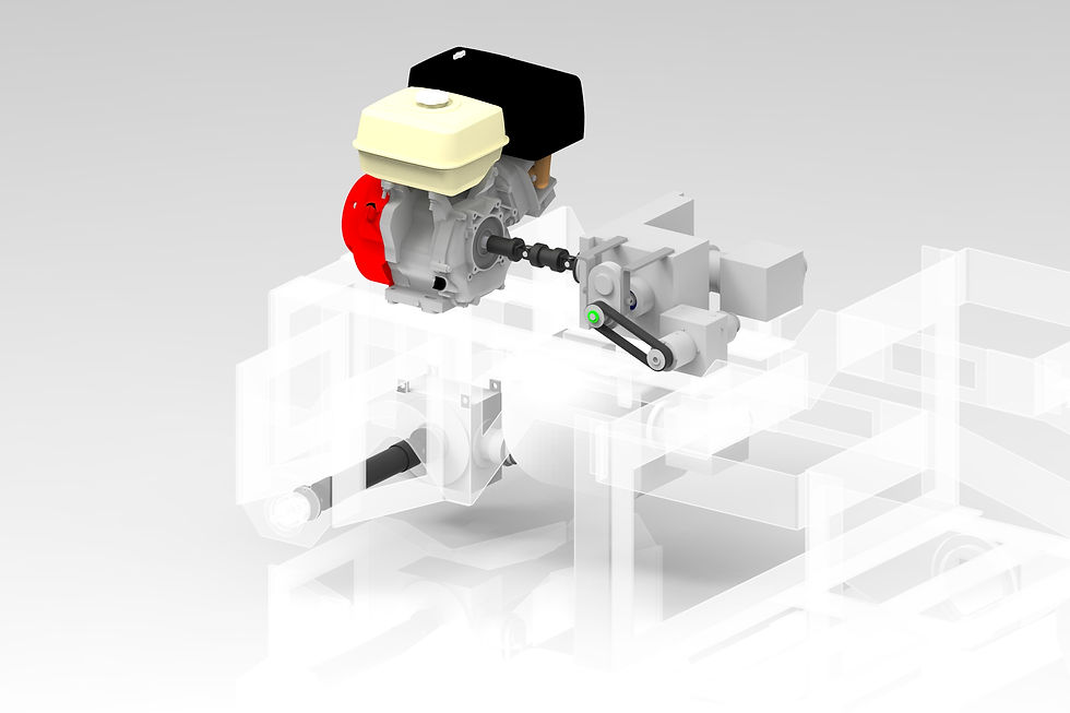

ST-16 Powertrain
In order to power the ST-16, a compact powertrain was developed around the provided Honda GX-120 engine. The main criteria for the powertrain was to allow easy maintainability and a low weight design where possible in order to make the entire sweeper more fuel efficient. At the same time, we challenged ourselves with some more complex solutions in order to further hone our design and cirtical thinking skills. The main components of the powertrain are outlined in further detail below.
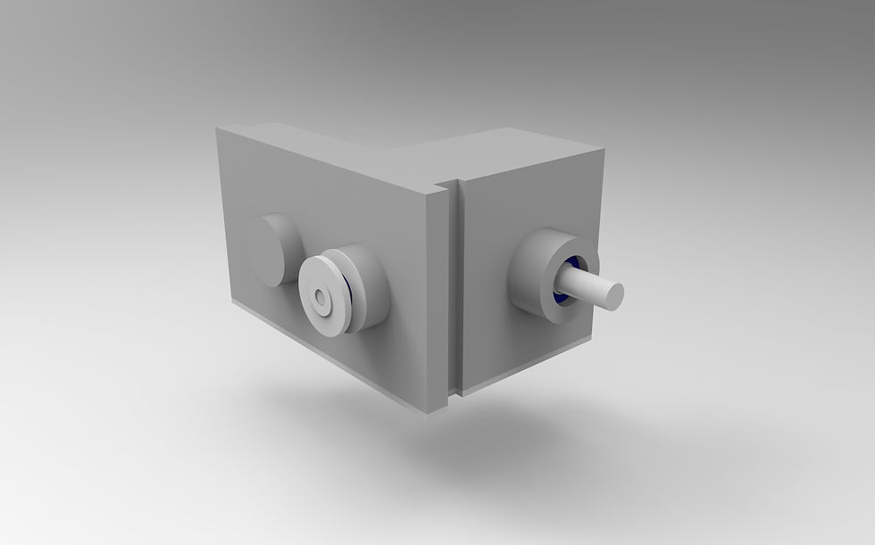

Single Stage Transmission
The first component following the engine is a single stage transmission (SST) which divides the powerflow of the engine into the two sub-systems; powertrain and brush system. The SST was given as a design restriction and marked as a necessary component in the project. As such, a very limited degree of freedom was given with the design of this component.
As part of the design process, the SST shafts were dimensioned for minimum diameter in order to transmit the given engine torque.


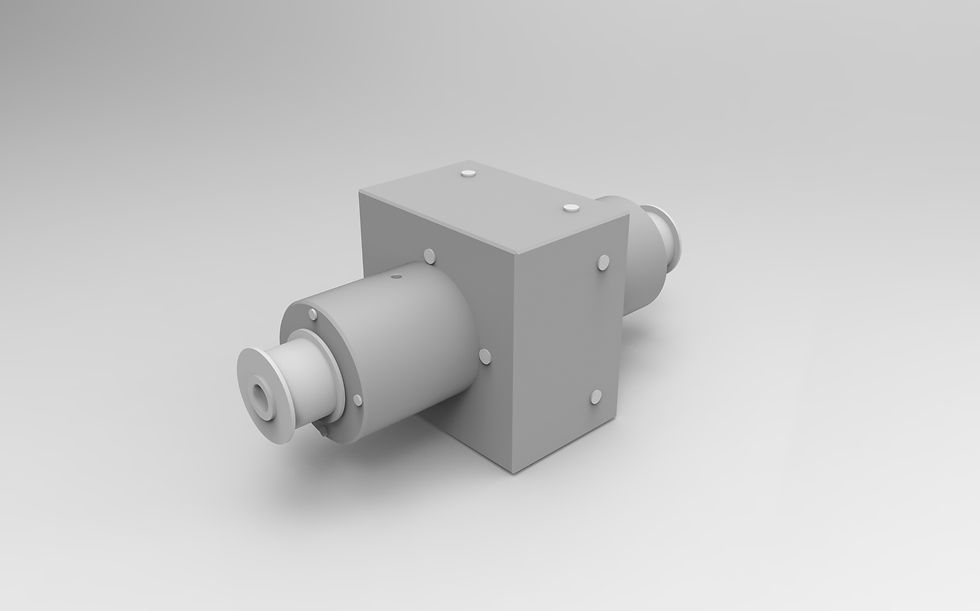
Hydraulic Gear Pump
Connected to the powertrain output shaft of the SST is a hydraulic gear pump. During our studies, we were extremely fascinated with the concept of hydraulics in technical systems and so in our sweeper we have implemented several hydraulic systems that require the gear pump to build up pressure in the hydraulic system.
Although the solution to use hydraulic components is in itself very expensive for such a small scale sweeper, the use of a gear pump proved to be the cheapest and most standard solution. Due to time constraints dimensioning of the gear pump was not carried out.

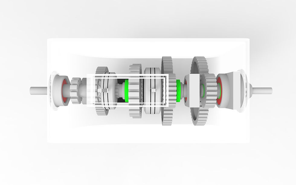
Multi-Disc Lamella Clutch
The clutch is an essential component in the powertrain that allows for powerflow control from the engine to the transmission. Additionally, clutches offer a form of safety in the system against overloading. In accordance with the hydraulic gear pump, the lamella multi-plate clutch is hydraulically activated. The compact size of a lamella clutch was important in order for the component to fit into the desired design space of the sweeper.
For the lamella clutch, the number of clutch plates and the transmissable non-slip torque was computed and dimensioned accordingly.


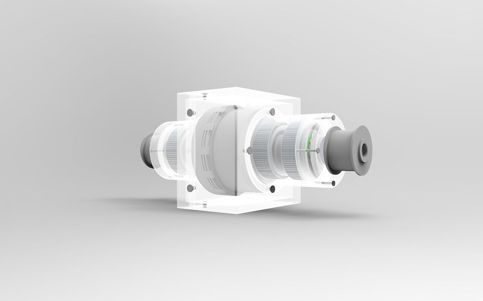
Transmission
The transmission of the ST-16 is the heartpiece of the powertrain (apart from the engine). The transmission provides two speeds for driving forward at the required 6 km/h (working speed) and 12 km/h (driving speed) and a reverse gear with maximum speed of 6 km/h. The shifting is accomplished through hydraulic cylinders located at the top box of the transmission. Due to time constraints these shifting units, however, have not been included in the CAD.
Additionally, full bearing lifetime dimensioning according to indstury standards and input shaft dimensioning according to DIN 743-1 were carried out for the transmission.
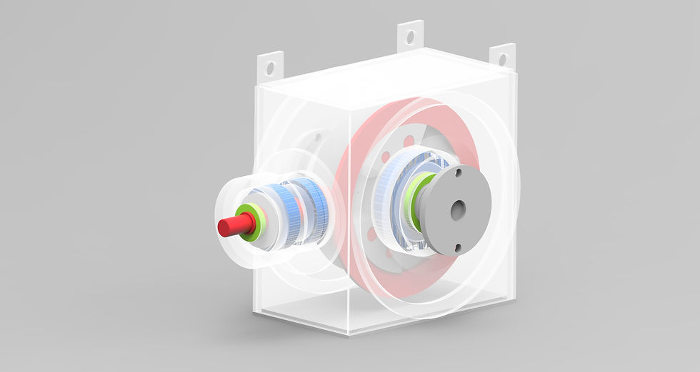

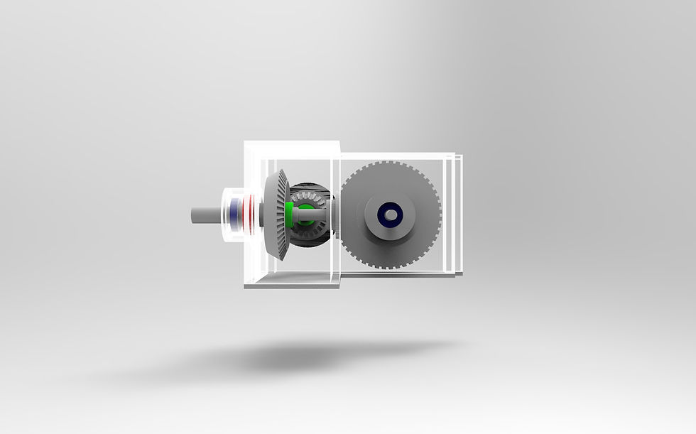
Spur Gear Differential
Perhaps the most surprising design choice leaving the hydraulic system behind is the use of a spur gear differential. The spur gear differential is a newer technological movement but brings with it several design benefits. The overall construction is lighter than a standard differential and the load distribution is improved. Additionally, the amount of axial forces within the differntial cage is also reduced due to the use of spur gearing. However, the factor of cost is one major drawback of such spur gear differentials.
The spur gear differential has fully dimensioned shafts for torque transmission.


ST-16 Brush System
The ST-16 brush system is packed with innovative solutions that fit into the small design space and adhere to the given project restrictions. Much like the powertrain, the main focus lay with easy maintainability and system expandability for future upgrades. To achieve this, the brush system is primarily designed in small sub-units which are connected via a belt drive system from the single stage transmission. Belt drive systems were the optimal design solution due to their low cost, low weight and easy routability. The brush system is composed of two main sub-system; the side brushes which collect and move dirt into the pathway of the rollerbrush and the rollerbrush which then transports the dirt into the waste containers. These two sub-systems will be outlined in more detail below.
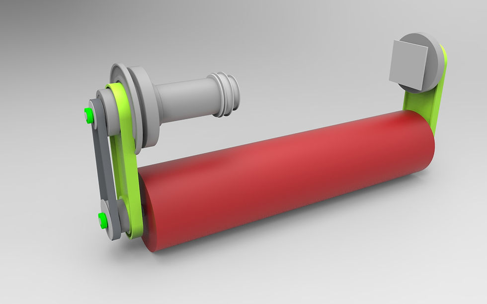
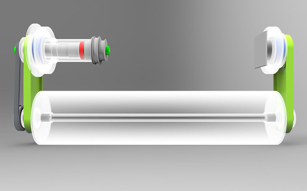

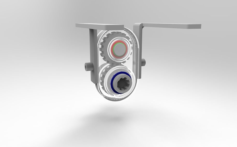
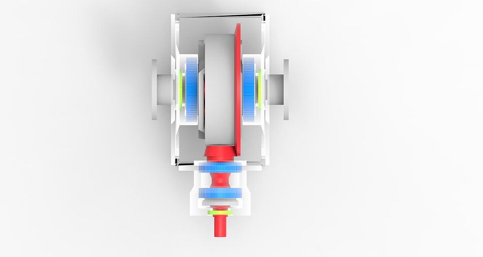
Roller Brush
The first stage in the brush system is the roller brush. A drive belt from the SST is picked up by the rollerbrush drive arm and transmitted via a secondary belt from the drive to the roller brush itself (depicted in red). The roller brush is supported by two polymer arms (neon green), with the none driven side being removable in order to quickly exchange the roller brush.
The contact pressure of the roller brush is ensured by torsion springs (blue) which are hidden inside the arm support structure. This design solution allows for simpler arm maintenance and a smaller overall design space.

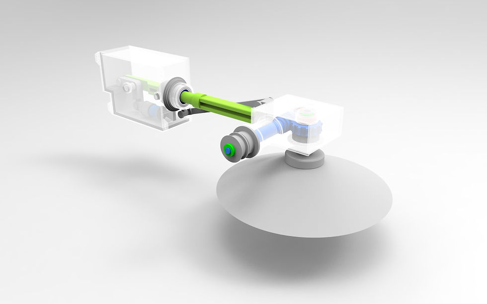

Front Side Brush
The design of the front brush provided many challenges due to several project restrictions. The brush may only possess a degree of freedom in pure vertical direction and the contact pressure must be ensured through the use of a dual spring configuration. In order to ensure a low ride height of the sweeper whilst maintaining a pure vertical movement, a special arm mechanism was designed that, within the defined degeree of motion, keeps the front brush box in a purely vertical motion.
The front brush is designed in two sub-systems (brush and arm mechanism) to ensure easier maintenance.
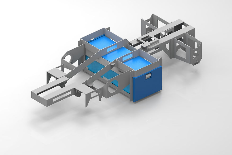
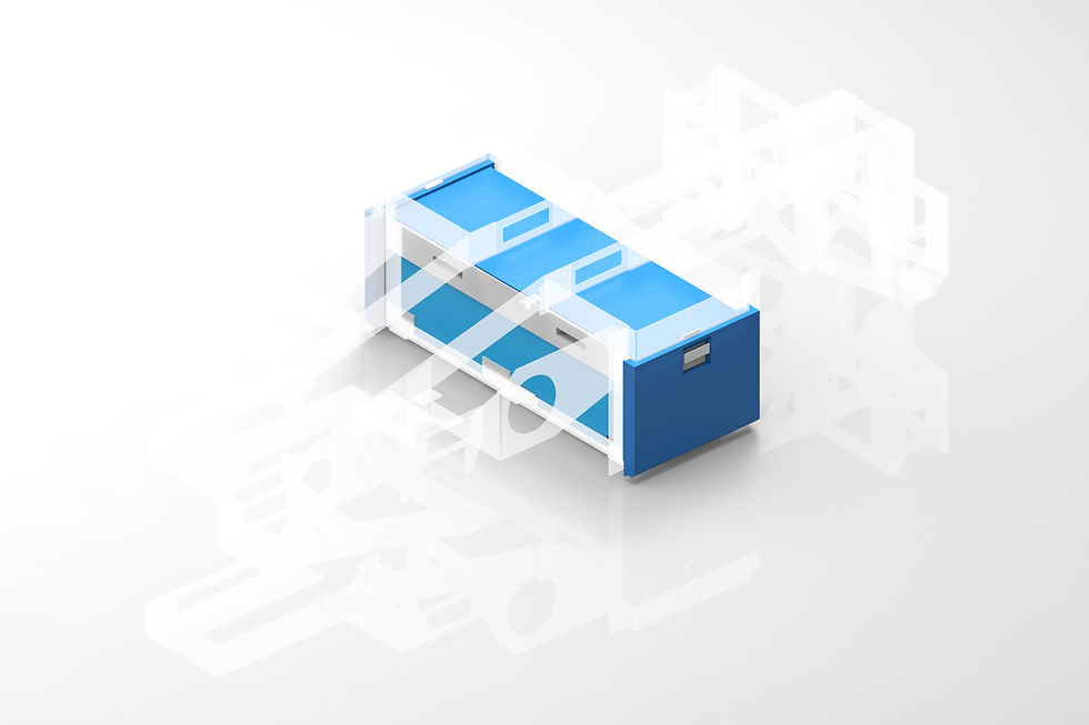

ST-16 Container System
The ST-16 waste container system is designed with ease of useability in mind. This has lead to a two bin system, where each bin can be removed from opposing sides. The combined bin volume corresponds to a total of 80 litres which is above the required 70 litre capacity. This allows longer operation times for the sweeper between emptying the waste containers. Each bin has several removable polymer covers which allow easy removal and transport of the waste containers. A handle lock system on each container prevents them from falling out during operation. Additionally, each container is equiped with self extending and self locking portable wheels. These wheels allow for sufficient height during container transport and function as guide wheels when the containers are then place back inside the sweeper. The containers are made primarily out of polymer with an additional steel support cage. This ensures an overall light weight design that can be handled by the sweeper operator.

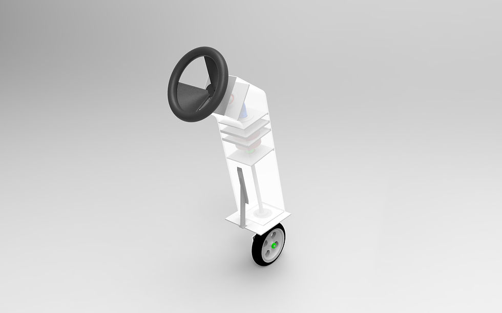

ST-16 Steering System
The ST-16 Steering System or Fork is designed to give the sweeper operator highly accurate control in tight spaces. To achieve this, a compact planetary gearbox with ratio 6:1 is integrated inside the steering column. The compact nature and optimal load distribution of the planetary gearbox has allowed for such a gear ratio to be implemented within the small design space of the steering column. Additionally, the front wheel is mounted on a single fork. This design choice allows for quick wheel access and maintenance. The steering wheel is kept simple; instead, a headsup tablet display provides the operator real time information on container waste level, driving speed, oil pressure and various cleaning modes.
The Team

Alex Rohregger
Team Manager and Lead Design Engineer Brush System
The role of team manager played and important part during the design project due to the strict deadlines and complexity of the solutions presented. Tasks of the team manager included distribution of team design tasks, deadline planning and overview of project operations and progress.
The role of design engineer for the brush system involved coming up with an expandable, maintabable brush system concept and the interconnectiong components and frame that would allow for the functioning of the entire system. Each component was taken from an initial principle sketch to a hand drawn technical drawing and finally transferred to CAD.

Gleb Gorbachev
Lead Design Engineer Drive System and CAD Visualisation
The role of design engineer for the drive system involved coming up with a simple yet intuitive drive system for small street sweepers. Given that the engine was provided as a project restriction, the drive system had to be designed around the engine. Each drive system component was taken from an initial principle sketch to a hand drawn technical drawing and finally transferred to CAD.
The role of CAD Visulatisation involved the collection of all CAD models and transferring them into a single coherent CAD prototype model of the entire sweeper system.

Joseph Miguel Leitmann
Project Planner and Design Engineer Sweeper Systems
The role of project planner was to work closely with the team manager in developing a realistic and achieveable project time plan. This time plan was maintained and updated through a Gantt chart and individual work time estimation and tracking. Additionally, the project planner secured all necessary project information and maintained it within the group database.
The role of design engineer sweeper systems was to aid the lead design engineers in their concepts and construction of the different sub elements. The design engineer sweeper systems ensured a succesful combination of both the drive and brush systems within the final sweeper design.

Jaivin Avasia
Lead Dimensioning Engineer and Norm Specifications
The role of lead dimensioning engineer was to work with both lead engineers in ensuring the safe dimensioning of major sweeper components during the design phase. The dimensioning processes were carried out iteratively during the design phase. The dimensioning engineer provided minimum dimensioning requirements for the proposed design solutions.
Additionally, the lead dimensioning engineer was in charge of ensuring that the design solutions adhered to the strict DIN-ISO regulations. This was especially important in ensuring that the theoretical knowledge of the lectures was also applied accurately according to modern engineering standards.

Gauri Gopakumar
Lead Design Engineer Bin and Steering System
The role of lead design engineer bin and steering system was to create a functioning container system for storing the dirt that was collected by the sweeper during operation. Crucial here was the incorporation of the container system within the existing sweeper infrastructure and under consideration of a limited design space and minimum volume requirements. Additionally, usability was a key issue for the container system.
Furthermore, the steering system of the sweeper was also designed with a key focus on ergonomics and providing high steering sensitive for fine sweeper motion in limited operation spaces.
Closing Remarks
It is important to keep in mind that the solutions presented here are first prototypes produced within the short time period of the project. At the same time, this design project was an excellent opportunity to apply the theory and techniques explained during the lectures of Mechanical Design within a realistic scenario. Finally, within the entire Mechanical Design Project, SweepTech scored and performed amongst the top 10% of all design groups (in total 109 groups partiticpated) and also had the honor of presenting infront of the Mecahnical Design professors, postgraduate teaching assistants and fellow students at the closing ceremony alongside two other teams.